

- 1. Product Overview
- 2. Performance Standards
- Key Technical Specifications
- 3. Key Features
- 3.1 Optimized Thermal Performance
- 3.2 Independent Compartmentalization
- 3.3 Superior Short-Circuit Withstand Capacity
- 3.4 Modular and Scalable Design
- 3.5 Flexible Cable Entry Options
- 3.6 Advanced Fault Protection System
- 3.7 High-Density Withdrawable Units
- 4. Auxiliary Circuit Design
- 5. Installation Guidelines
- Standard Cabinet Dimensions
- 6. Applications
- 7. Conclusion
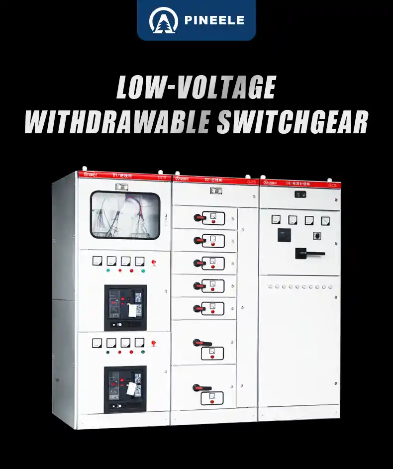
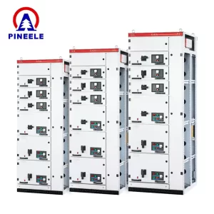
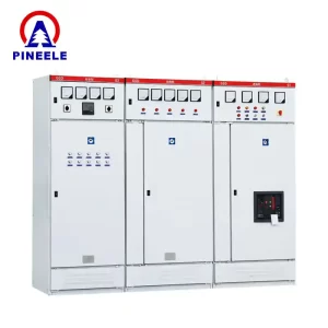
1. Product Overview
TheGCS LowVoltage Withdrawable Switchgearis an advancedpower distributionsystem designed to meet the demands ofindustrial automation, power plants, substations, and commercial facilities. Compliant withIEC 439-1, GB 7251, and ZBK 36001standards, it offersmodular design, high safety, and flexible configuration, making it a preferred choice for power distribution and control applications.
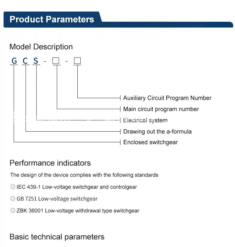
2. Performance Standards
The GCS switchgear adheres to international and national industry standards:
✔IEC 439-1– Low-voltage switchgear and controlgear
✔GB 7251– Low-voltage switchgear
✔ZBK 36001– Low-voltage withdrawable switchgear
Key Technical Specifications
| Specification | Value |
|---|---|
| Main Circuit Rated Voltage | AC 380V (400V, 660V) |
| Auxiliary Circuit Rated Voltage | AC 220V, 380V (400V), DC 110V, 220V |
| Rated Frequency | 50Hz (60Hz) |
| Rated Insulation Voltage | 660V (1000V) |
| Rated Current | Horizontal Busbar ≤ 4000A/Vertical Busbar 1000A |
| Short-Time Withstand Current (1s) | 50kA, 80kA |
| Peak Withstand Current (kA) | 105kA, 176kA |
| Power Frequency Withstand Voltage (V/min) | Main Circuit 2500V / Auxiliary Circuit 1760V |
| Busbar System | Three-phase four-wire / Three-phase five-wire |
| Protection Level | IP30, IP40 |
3. Key Features
TheGCS switchgearprovidesenhanced reliability, safety, and flexibility, making it ideal for demanding industrial power distribution systems.
3.1 Optimized Thermal Performance
✔ Efficient heat dissipation through optimizedbusbar layout, reducing temperature rise on connectors, terminals, and cable heads.
3.2 Independent Compartmentalization
✔ Functional units arephysically separated, ensuring that faults in one unitdo not affect other components, improving system reliability.
3.3 Superior Short-Circuit Withstand Capacity
✔ Thehorizontal busbar designenhances dynamic thermal stability, allowing the switchgear to withstandshort-circuit impacts up to 176kA.
3.4 Modular and Scalable Design
✔ EachMCC (Motor Control Center) cabinetcan accommodate up to22 independent circuits, supporting large-scale industrial operations.
3.5 Flexible Cable Entry Options
✔ Supportstop, bottom, front, or rear cable entry, making installation and maintenance more convenient.
3.6 Advanced Fault Protection System
✔ Equipped withcurrent-limiting reactorsthatstabilize bus voltage and mitigate short-circuit current surges, improving overall system protection.
3.7 High-Density Withdrawable Units
✔ Designed with32 pairs (or 20 pairs) of secondary plugs, ensuring seamless integration withautomation and control systems.
4. Auxiliary Circuit Design
Theauxiliary circuitis designed following theTechnical Provisions for Electricity Used in Thermal Power Plants, ensuring compatibility withpower substations, industrial plants, and data centers.
This system providesmodular power inlet units, feeder units, and MCC (Motor Feeder) operational modules, allowing forprecise power control and efficient distribution.
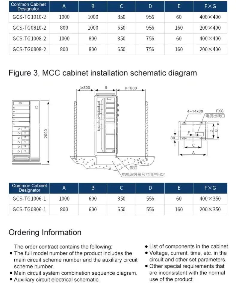
5. Installation Guidelines
Below is thestandard dimension chart and installation schematicfor GCS switchgear cabinets.
Standard Cabinet Dimensions
| Cabinet Model | A (mm) | B (mm) | C (mm) | D (mm) | Description |
|---|---|---|---|---|---|
| GCS-TG1010-4 | 1000 | 1000 | 850 | 956 | Contact Cabinet |
| GCS-TG0810-4 | 800 | 1000 | 650 | 956 | Incoming Cabinet |
| GCS-TG1008-4 | 800 | 800 | 650 | 756 | Incoming Cabinet |
| GCS-TG0608-4 | 600 | 800 | 450 | 756 | Incoming Cabinet |
📌Installation Considerations
- Minimum clearance of 800mmshould be reserved forcable trenchesto ensure proper cable layout.
- Maintainat least 1800mm clearancebetween the top of the cabinet and the ceiling for ventilation.
- Use aV-shaped reinforced concrete foundationfor enhanced structural integrity.
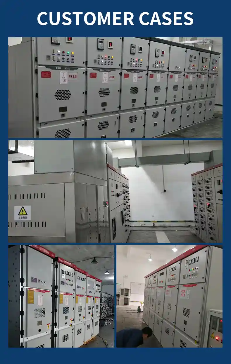
6. Applications
TheGCS switchgearis extensively used in power distribution systems for various industrial and commercial applications, including:
✔Power generation plants, substations, and data centers
✔Rail transit systems, airports, hospitals, and commercial buildings
✔Petrochemical, steel, and manufacturing industries
✔Renewable energy integration (wind power, solar PV systems)
Due to itsmodular architecture, high safety standards, and reliable performance, the GCS switchgear remains thepreferred choiceformission-critical power distribution systems.
7. Conclusion
TheGCS Low Voltage Withdrawable Switchgearoffershigh reliability, scalability, and enhanced safetyforindustrial power distribution. Designed formodern automated systems, it meets the highest standards in terms ofperformance, efficiency, and flexibility.
📩Contact Us: [email protected]
📞Phone Consultation:+86-18968823915