A 220 kV substation plays a vital role in the electrical power transmission network. It is a high-voltage substation used to step down voltage from transmission levels to distribution levels, typically converting 220 kV to 110 kV, 66 kV, or lower voltages. The effectiveness of a 220 kV substation depends heavily on the precision and clarity of its layout drawing. This article provides an in-depth look into the standard 220 kV substation layout drawing, its technical details, design philosophy, component arrangement, and safety measures.
A substation layout drawing is a visual representation of how different electrical and structural components are arranged within the substation boundary. These drawings are essential for civil engineers, electrical designers, maintenance teams, and utility planners. In a 220 kV system, the layout drawing typically includes:
Here is an overview of the core equipment in a typical outdoor 220 kV substation:
| Equipment | Function |
|---|---|
| Power Transformer | Steps down voltage from 220 kV to lower levels |
| Circuit Breaker | Disconnects the circuit during faults |
| Isolator | Provides physical separation for maintenance |
| Busbars | Conductive bars to distribute electricity |
| Lightning Arrester | Protects equipment from voltage surges |
| CTs & PTs | For protection and metering |
| Control & Relay Panels | House automation and protection systems |
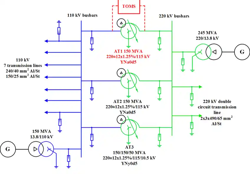
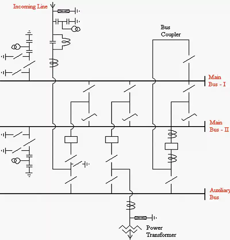
This diagram shows how the electricity flows through the substation using symbols for transformers, breakers, and lines.
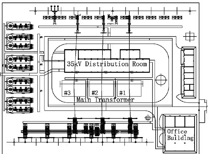
It gives a top-down view of all major equipment and their spatial relationship.
Shows the civil structures such as foundations, trenches, cable ducts, and fencing.
A vital drawing showing the earthing mesh that ensures safety and fault current dissipation.
| Parameter | Standard |
| Rated Voltage | 220 kV |
| Insulation Level | 1050 kVp lightning impulse |
| Rated Frequency | 50/60 Hz |
| Short-Circuit Rating | 40 kA for 3 seconds |
| Neutral Grounding | Solidly grounded |
| Protection Scheme | Distance + Differential + Backup Overcurrent |
| Description | Clearance |
| Phase-to-phase | 3000 mm minimum |
| Phase-to-earth | 2750 mm minimum |
| Vertical clearance | 5000 mm minimum |
| Clearance around equipment | 1500–2000 mm |
These clearances are defined as per IEC and local utility standards.
PINEELE provides full engineering services for 220 kV substations:
📧 Contact: [email protected]
📞 Phone: +86-18968823915
💬 WhatsApp Support Available
A: Typically between 30,000 to 50,000 square meters depending on the number of bays and configuration.
A: Yes, with Gas Insulated Switchgear (GIS), but the cost is significantly higher.
A: Generally 12–18 months including civil, mechanical, and electrical works.
A detailed and accurately executed 220 kV substation layout drawing is foundational for a safe, reliable, and scalable power system. Whether it’s step-down transformation, power distribution, or renewable integration, a 220 kV substation ensures seamless energy flow across regions.
With years of high-voltage engineering experience, PINEELE stands as a trusted partner in kv substation guide design, manufacturing, and deployment.
“Powering the Future, Engineered by PINEELE”